Finishing Up the Satellite Yagi

Over the past week I finished the satellite Yagi. I added a VHF Yagi and a band splitter to the UHF Yagi that I constructed first.

Kent Britain, the designer of the antenna, wrote that you can obtain good results with a 2-element 145MHz antenna, but I decided to stay on the safe side with a 3-element antenna, like the one described by Richard Crow. I noticed that Crow’s 3-element antenna was a little different than Britain’s, and decided to build to Britain’s measurements. I first cut the elements out of the same stiff copper wire that I used for the 435MHz Yagi. I was not sure, however, how to combine the two antennas into a single structure. Britain suggested to mount the VHF antenna behind the UHF antenna, on the same boom and on the same plane. This makes it easy to transport and store the antenna, since it is flat, but the boom is pretty long. Crow mounts the antennas side by side; this is easy with his very lightweight construction, but would be harder with wood booms. Shamai Opfer suggested to mount them on separate booms connected by hinges, so I can store them together flat but flip them into a crossed configuration for operating.

I eventually decided to start by mounting them one behind the other on the same boom, and to saw them apart later if I want to try a different configuration. I initially mounted the VHF Yagi 6 inches behind the UHF one, but when I re-read Kent’s article I realized that h wrote that they must be spaced only 3″ apart. So I removed the VHF elements, drilled new holes in the boom, and mounted them in the correct places. I soldered a connector to the VHF Yagi and verified that it was a good match to the transceiver. I was; no tweaking was necessary. I was also able to receive stations communicating using Morse code through VO-52, a satellite with a linear transponder whose downlink is on 145MHz.

To communicate through satellites with the FT-857, I also needed a band splitter, a 3-port filter that would allow the single VHF/UHF connector of the radio to be connected to the two antennas (you don’t need it if you use separate UHF and VHF radios). Kent Britain’s article describes a simple splitter consisting of two 3-component filters, a high-pass for the UHF port and a low-pass for the VHF port. I did not have capacitors with the values in Britain’s article, so I designed my own splitter with Elsie, a filter design program.
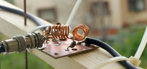
Elsie has an option to design diplexers, which are band splitters that aim to keep the impedance at one port constant over a large frequency range. Diplexers are used following mixers, for example, where you want a proper termination for the image frequency and to various spurious frequencies that the mixer might output. You can use a diplexer as a band splitter, but if you don’t need constant-impedance termination you have much more freedom to design the low-pass and high-pass filters. I designed the two filters by telling Elsie to design a Chebychev filter and playing with the cutoff frequency and ripple settings until I got the capacitor value I wanted in combination with very little attenuation at in the 145 and 435MHz bands. My capacitors were one 12pF cap for the 145MHz low-pass filter and two 5pF units for the 435MHz high-pass. This generated two inductor values. I then used Elsie inductor calculator to come up with appropriate air inductor designs. I played around a bit to get a sense of what inductance different diameters and turn counts  gave. When I got close, I designed the actual filters by specifying the diameter and number of turns. For the UHF filter, I specified 3 turns and a 0.5cm diameter; a length of 0.9cm gave the proper inductance. For the VHF filter, I specified 6 turns and a 1cm diameter, which required a 1.9cm length. I wound the two VHF inductors from the same piece of wire and then bent it so that the inductors were at a 90° angle, to minimize coupling. The UHF inductor was mounted upright, also at a 90° angle from the VHF coils. The wire for all inductors came from a choke from a broken PC power supply.

I connected the antennas and the radio to the splitter and tested the match. I was almost perfect on both UHF and VHF. I could open repeaters on both 145MHz and 435Mhz.

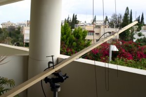
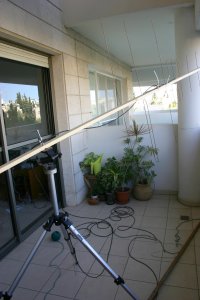
I clamped the wooden boom to a camera tripod, as you can see in the picture at the top. The weight of the antenna is not balanced on the tripod. To relieve some of the force it applied to the tripod’s head, I tied the back of the boom to a leg of the tripod with a cord. It works, but I’ll need to find a better solution.
The next step was to try the antenna on an FM-repeater satellite. Yesterday two of them passed overhead at reasonable hours, allowing me to try satellite communication for the first time. The first was AO-27, a very old satellite (launched in 1993). It’s web site specifies a schedule, which suggested that only its telemetry beacon would be active when it was over me. I tried to receive the UHF signal nonetheless. When it came over the horizon, I could hear the quieting in the receiver, but then heard a voice station calling. I replied and was able to work that station and 3 more. The next repeater sat to pass over was AO-51, whose repeater is active all the time, and which I was able to hear well when I only had the UHF antenna. AO-51 was much more crowded, with stations transmitting at the same time (and causing severe interference), but I was still able to work a few stations. Tracking the Doppler shift on FM is not hard; I’ll explain the issues in another post. I tracked the location of the satellites by manually rotating the tripod a couple of times during each pass.

I am very pleased that the antenna allowed me to communicate through the satellites. The antenna is sitting in my balcony. As you can see in the picture, it is essentially indoors, facing a large window. There’s a ceiling above it; the walls around it and the ceiling are all reinforced concrete. From the balcony, about 120° of the sky is visible, towards the east and north. When satellites are to the west or south of me, I can’t see them at all. But in spite of all of these limitations, I was able to communicate through the sats.
Repairing a Deaf Softrock Transceiver

My Softrock Ensemble RXTX transceiver has gone deaf a while ago. It was working very well, allowing me to to experiment with WSPR and PSK31. But at some point it gradually got deaf, until it could receive nothing. It could still transmit fine.

I tried to fix it, trying the easy things. I checked that the Si570 oscillator was working and changing frequencies; it was fine. I also inspected the board visually for bad solder joints, but didn’t see anything obviously wrong. I don’t have a signal generator, so I could not easily check where the input signal is lost in the receive path.

Yesterday I decided to give it another go. I used a 1-transistor crystal oscillator that I put together as a signal generator. It had a 10.116MHz crystal. I hooked its output to an oscilloscope, verified that it was oscillating, and that the signal was not too large (it was around 200mV peak-to-peak). I hooked its output to the input of the Softrock and started tracing with the scope’s probe.

I could still see the signal at the antenna side of T4. So the low-pass filter was fine (the signal was also much cleaner at that point, because the low-pass filter removed the harmonics from the oscillator’s output). Next, I checked resistors R54 and R53, which feed the RF signal to the detector. No signal. This narrowed down the search considerably. Testing both sides of inductor L4 showed that it was blocking the signal. From the top side of the board, the joints did not look good; there was no solder creeping up the wires. I unsoldered it and discovered that one wire was not tinned properly. I scraped the enamel off the wire, tinned it, and soldered it back in place. Now I was able to see the audio-frequency signal at the output of the receiver on the scope, indicating that the receiver was now working. I’m using it right now on 14MHz WSPR.

Robby’s building instructions tell you to remove the enamel very carefully off enameled wire, and that not doing this leads to many of the problems with the kits. I did not heed the warning carefully enough, I guess. I still find the evolution of this fault interesting, in that the radio was working fine for a few months before the soldering fault showed up.

Building the UHF Cheap Yagi for Satellite Communication

One of the reasons to buy the FT-857D transceiver was to experiment with satellite communications. There are many antennas that are suitable for satellite communications in UHF and VHF. After investigating a bit I discovered articles on so-called cheap Yagi antennas that seemed easy to build. I started with the 435MHz Yagi, which is a little easier to build than the 144MHz version.

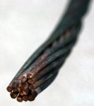
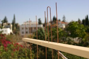
The antennas were designed by Kent Britain starting in 1994. Kent’s web site contains one document with designs for the satellite bands and another with construction data for other bands. Kent suggest to build the boom from wood, which is what I did. For the elements I used stiff copper wire that I salvaged from a piece of power line that the local utility discarded when they replaced a power pole near my home. At least for the 435Mhz elements, which are about 35cm long, it is stiff enough. The boom is made of a 240cm piece of 18mm-by-36mm lumber. The 6-element Yagi I built does not use the entire 240cm length, only about 75cm. I drilled the holes for the elements with a hand drill.

Three articles by Richard Crow on the AMSAT web site shows how to build satellite UHF and VHF Yagis with a boom made of a lamination of foam board. For some people they might be easier to build than the wood-boom Yagis, and they are lighter. I found that constructing the wood boom with hand tools very easy; I think that cutting and laminating foam boards would have taken me more time.

The antenna was as easy to build as Kent claims. I just built the antenna according to the measurements in his article (Crow gives the same dimensions except for the separation in the driven element, which Kent wrote to me is not critical). I then soldered the coax and tested. The antenna had low SWR without any tuning.

On the right you can see the discarded power line I used for the elements and the connection of the feed line to the driven element.

After I finished building the antenna, I tried to receive a signal from a couple of satellites, but I heard nothing. The satellites I tried to receive were operational according to the AMSAT web site (click on Sat Status), they were overhead according to the satellite tracking module of Ham Radio Deluxe, but even when the receiver was tuned to the correct frequency and the antenna aimed in the general direction of the satellite, I could not detect any signal. I did not expect this to be easy, so I was not surprised at all.

The next morning I tried again. Again I could not detect the first satellite I tried to receive, but the second attempt was successful; I was able to hear the Morse beacon of CO-58 very clearly. I was very happy. Experiencing the Doppler shift for the first time was really interesting.

[An update from March 18: I was also able to hear people communicating through the FM repeater of AO-51; very cool]

To actually communicate using satellites, I’ll also need a 144Mhz antenna. Richard Crow’s construction articles show how to mount the two Yagis side by side on a camera tripod. The configuration is the same as when two Yagis are mounted on azimuth-elevation rotators. It works on a tripod because Crow’s Yagis are very light; I am not sure that this setup will work well with wooden booms. Kent Britain’s article shows a 5-element 435MHz Yagi and a 2-element 144MHz Yagi on the same boom, one behind the other. This is more convenient, but would be a bit awkward with longer antennas. The Arrow II antenna puts the two Yagis on the same length of boom, one vertically and the other horizontally. This is more compact than putting them one behind the other, but it makes it hard to stow and transport the antenna. This is not an important concern if you keep it mounted outdoors, or if you take it apart when you stow it, but the cheap Yagis are not easy to take apart. I’ll have to ponder this issue for a while.

Satellite communication with a single transceiver also requires a band splitter; fortunately, Kent Britain’s article also shows how to build a simple band splitter; I’ll probably build it after I build the 144MHz Yagi.

An Update on the Coax Transmitting Loop

I’ve been using my two transmitting loops for a while now, so I now have a better sense of how they perform and of their usability.

I don’t use the “unusual” loop much. According to the KI6GD Magnetic Loop Antenna Calculator, it should be about 50% efficient (this figure depends on the material, aluminum, the diameter of the conductor, the circumference, and the frequency, 14MHz). I can tune it, but pushing the gimmick capacitor in and out of the tube is not a convenient tuning method; this is why I don’t use it much.

It’s a little difficult to tell how efficient the coax loop is. The calculator program says it’s 32% efficient on 14MHz, but it is not made of solid copper but rather the coax braid and inner conductor. The two N connectors also add resistance, but I don’t know how much. The program estimates the resistance of the loop to be 0.078Ω, so if the coax and the connectors add something in this range (which is very little; if you use the coax and connectors as 50Ω transmission lines, 0.078Ω is almost nothing), the antenna could be a lot less efficient than the 32% that the program calculates. On 7MHz the theoretical efficiency is only 4%, 12% on 10MHz, 66% on 21MHz, and 84% on 28MHz.

I use mostly the coax loop because it is easy to tune. Its variable capacitor, which you can see in the picture, is driver by a vernier dial, so it’s fairly easy to tune. I can now do it by ear most of the time: I turn off the automatic gain control (AGC) in the receiver and tune to maximum noise. This often gives acceptable SWR. If not, I reduce power to about 1.25W (5W in AM mode) and tune by watching the SWR meter.

When I started using the loop with the FT-857D, I wanted to be able to transmit on 7MHz, to participate in the local weekend net. The tuning capacitor is a 4-section type with a common shaft. I initially soldered the loop to two sections in a split-stator configuration (the loop was connected to two stators and the rotors are connected by the shaft and floating; this puts the two sections in series without a moving contact). The antenna did not tune on 7MHz, so I connected the two remaining sections too. This allowed it to tune from below 7Mhz to about 24Mhz. In the picture above you can see one section-to-section jumper in place and one half connected; the jumpers are made of RG58 coax.

In this configuration, I was able to participate in the 7MHz net, but my signal was obviously weak (even in the best case that the loop is indeed 4% efficient, I was only emitting 4W peak). Since the higher bands began to open in the last few days and since my signal was very weak on 7MHz, I decided to modify the antenna to target higher bands. I unsoldered the jumbers to leave only 2 sections connected. The loop now tunes from the upper part of the 7MHz band to 30MHz or so.

Over about four weeks, I was able to make PSK31 contacts on 14, 18, and 21MHz, JT65A contacts on 14MHz (my serial interface injects noise on the 21Mhz JT65A frequency; I’ll investigate, but so far this prevented me from working there), and SSB contacts on 14Mhz and 21MHz. I did not manage to operate when the 28MHz band was open, but I expect that I can make contacts there too.

Working PSK31 and JT65A stations with this antenna on the higher bands is easy. Stations usually hear me and reply. In PSK31 I worked stations from all over Europe; on JT65A also in the Philippines and Sri Lanka. SSB is not so easy. In many cases I can hear the a station very well but it does not hear me. Working with such a small antenna requires patience. But I did manage to work European stations on SSB. I normally get weak signal reports. But when conditions are good, the loop permits clear and pleasant communication; I was able to have a long chat today with a German station 2800km away from me. A big antenna on the other side obviously helps too.

The antenna does not arc across the capacitor even with 100W SSB and 50W in digital modes. I was worried about this possibility but it did not happen.

Small loops have a narrow bandwidth, but I have not found this to be too annoying. Once I tune it in a given part of the band, say 21Mhz SSB, I can tune the transceiver up and down quite a bit without having to retune. Maybe this is an indication that the antenna is less efficient than the KI6GD Magnetic Loop Antenna Calculator estimates. But it’s convenient.

Finally, the experience with the loop so far validates my decision to buy a 100W transceiver. At some point I considered buying the FT-817, which outputs only 5W but is otherwise very similar to the FT-857D. An inefficient antenna and a low-power transceiver would not be a good combination; but with a relatively inefficient antenna and a high-power transceiver you can communicate.

Building Chavdar Levkov’s Active Wideband Loop

A little while ago I discovered on the web yet another design for an active wideband receiving loop antenna, by Chavdar Levkov. Chavdar clearly analyzed both the requirements that the amplifier needs to satisfy and the circuit that he built very carefully. Therefore, I hoped that this antenna would outperform my existing active wideband loop, which uses a different amplifier, designed by John Hawes. I use my wideband a lot; it is sensitive (much more than the active whip) and does not require tuning (unlike the tuned receiving loop and the transmitting loop). Therefore, I really welcomed the possibility of a more sensitive receiving antenna that would still not overload.

The basic difference between Chavdar’s amplifier and John Hawes’ is that Chavdar’s input stage is a grounded base amplifier with a very low input impedance, which matches the impedance of the loop better than Hawes’ common emitter amplifier. The grounded base amplifier drives a common emitter stage, so Chavdar’s amplifier is also a bit more complicated to build, but not by much. When I wrote to Chavdar with some questions on his design, he compared it to Hawes’ and wrote back that he thought that his own design has higher dynamic range and higher gain at lower frequencies, but perhaps also more noise at high frequencies. I decided to give it a try (particularly since I wanted another antenna of this type anyway, because the existing one is tied all the time to a WSPR spotting activity).

One interesting aspect of Chavdar’s design is the use of networking cable rather than a coax. The CAT5 or CAT5e cable carries the power to the amplifier and the signal back on two separate twisted pairs; in my earlier active antennas I used the conventional method of putting the DC and RF on the same coax and separating them with bias tees. I was a bit hesitant to use networking cables, mainly because I did not want to deal with the 8-pin sockets, which won’t fit into a 0.1″ breadboard hole pattern. Chavdar encouraged me to use networking cables and sockets, because they are cheap, deliver high performance, and they eliminate the need for bias tees. I eventually realized that if I mount the sockets upside down and wire them ugly style, I could probably use them. It worked. (I later discovered that this is exactly how Chavdar mounted the sockets; I didn’t study the pictures in his article carefully enough.)

Before I could put the sockets into the circuit, I had to figure out how to ground the cable shield on the receiver side but not on the antenna side. Until then, I never paid any attention to shielding in these cables. I looked at one plastic connector connector and couldn’t figure out where the shield connection was. It was not there at all, because some of these cables are unshielded (they are marked UTP) and have plastic unshielded connectors. Shielded cables, marked STP or FTP, use connectors with a metal shield that’s connected to the cable’s shield. After I figured this out, I mounted the two sockets; on the receiver side, I mounted a metal-shielded socket by soldering it to a scrap PCB; on the antenna side, I super-glued a plastic socket to the PCB.

The rest of the construction is pretty similar to the way I built Hawes’ amplifier, both in terms of circuit construction and in terms of the enclosure and loop connection. Chavdar’s design used a 10V regulator on the antenna side, powered by an 12V input supply. Chavdar used a 7810 fixed-voltage regulator which I did not have, so I used an adjustable LM317 regulator. This caused me a some problems. I initially put a REG1117 regulator in the circuit. It promptly died. I replaced it and the replacement also died almost immediately. At that point I read the data sheet more carefully, and realized that the regulator needs 2 protection diodes if it is used with large-value capacitors. I used a 10μ tantalum cap on the input terminal and 22μ tantalum caps on the output and adjustment terminals; these caps can easily provide enough current to destroy the regulator when you power the unit down, and they did. I then put in the diodes, replaced the dead REG1117, and put in a new regulator (this time an LM317, but I could have used a REG1117). Now the regulator section works fine.

On the receiver side, you need a unit with an RJ45 socket, BNC to connect the receiver, and DC power input (and some filtering for both, which I did not yet put in). I initially mounted all 3 sockets on a piece of PCB, for lack of an appropriate enclosure. A little later, I realized that since the amplifier unit contains a voltage regulator, there is no need to power the amplifier using a regulated 12V supply; an unregulated one would work just fine. I therefore added a little mains transformer, diode bridge, and filtering (a pi network with two electrolytic caps and an inductor on the receiver side. There’s still no enclosure, but it’s more convenient than before. It looks weird, but it works.

I did not compare the antenna carefully to the one with Hawes’ amplifier. The loop element I used in both antennas is exactly the same, so comparing the antennas should show any differences between the amplifier circuits. But I have not done that. In casual listening, the antenna performed very well. During the SSB context over the weekend, I was able to hear many US SSB stations; I never heard any with the Hawes loop at the same location (ouside 1st floor balcony in an urban area about 10,000km from the US east coast) . This does not say much, because the contest brought many strong stations to the air, and propagation conditions were good over the weekend. But this definitely made me happy. The antenna performed fine from 3.5MHz to 24MHz (28MHz was closed when I was listening). It also receives the airband (VHF AM) and 144MHz and 430MHz, but on these frequencies it’s a little less sensitive than a 144MHz dipole. It works on MF, but not as well as I hoped; I can receive BBC World on 1323kHz, but not as well as in my car.

I now agree with Chavdar that using networking cables and connectors for receive antennas is a good technique. I plan to replace the cabling in my tuned-loop amplifier, because it needs not only RF and power, but also tuning voltage for the varactor diodes; on a CAT5e cable, I can just use a third pair for the control voltage.

I am indebted to Chavdar for both putting the design and the detailed analysis on the web and answering all my questions via email; thanks!

Linux Serial Server Now Working with HRD and FT-857

After some additional efforts, I managed to get my Linux remote serial server to work with HRD; now HRD running on Windows can control my FT-857 when it is connected to a Linux box.

Getting there required resolving three issues. One was getting the code that configures the serial port to work correctly. It had some bugs in this code initially, which prevented the code from actually talking to the radio. The second was a new protocol command that I did not see before. HRD uses this command to set the frequency of the radio. I initially treated it like the normal command that sends data to the radio. This did not work. Snooping on the protocol with Wireshark showed that the server should not respond to this message at all; I removed the response, and it started working. The final issue involved the command that writes configuration parameters to the radio’s EEPROM, command BC in the CAT protocol. This is an undocumented CAT command (and a very useful one). For some reason, HRD expects a 5-byte reply from the radio to the command. The radio apparently does not reply, so the serial read attempt times out. I did not initially implement timeouts in my code, so it just got stuck. When I added timeouts (which are also useful in other cases), the code was finally able to fully control the radio.

Here is the code; it’s very preliminary and only tested with the FT-857.

Reverse Engineering the HRD Remote Serial Protocol

Ham Radio Deluxe (HRD) is a free program that servers as a user interface to radio transceivers. Modern transceivers can be controlled either from their front panel controls (if they have a front panel), or from a computer through a serial or USB connection. HRD allows you to connect to a radio, or even to a few simultaneously, and to control it through on-screen controls. Its user interface is absolutely fantastic. It comes bundled with a bunch of other radio-related programs, but in this post I am only interested in HRD itself.

One cool and useful feature of HRD is that it can be used to control a remote radio. You run an HRD server program on the computer to which the radio is connected. You run HRD itself (the user-interface program) on another computer, and tell it that the radio is connected to the first computer. HRD establishes a network connection with the remote computer and controls it.

I want to use this feature, but I want to connect the radio to a computer running Linux, not Windows (I have good experience with remote radios connected to a Linux box, whereas I don’t like to run Windows remotely). Alas, HRD and it’s remote server only work on Windows. Searching for Linux server programs that would work with HRD revealed that none exist, and that Simon Brown, the developer of HRD, does not want to release a specification of the remote protocol or code that would explain the protocol. (I didn’t try to figure out the reason for this, but I assume he has a good reason not to release the protocol/code, and I respect that; I am grateful for the program itself and for the public specification of another important protocol related to HRD, the one that allows other programs to talk to HRD.)

Serial communication is not terribly complicated, so I thought that I might be able to reverse engineer the protocol and to write the Linux server code myself. I was right. I now have Linux code that HRD thinks is its remote server. It’s not finished yet, and I didn’t connect the radio yet to the Linux box, but this should be just a matter of time before it all works together. The rest of the post explains how I figured out the protocol. I’ll share the code itself once it’s actually working with a radio (if you’d like to help develop and test the code, please drop me a line).

I initially assumed that the protocol would be pretty simple, and decided to figure it out using a Java program that I could configure either as a server, playing the role of a remote computer connected to a radio, or as a client, playing the role of the HRD GUI program. I would run the program as a server and try to connect to it from HRD. My code would dump the data it received, and this would tell me how HRD starts the exchange. I would then run it as a client, connecting to HRD’s own server, and send the data I received previously. The real server would respond, and now I would know what the first response looks like. I did this, repeating the process for 3 different request-reply exchanges. The messages were pretty simple, and I was able to determine where the fields were within the message and what they meant. For example, I discovered that messages start with a 4-byte length field, followed by a 4-byte fixed signature (HRD*), and so on. I did make a few mistakes (initially I thought that the length field was fixed, for example), and there might be fields that were always zero in my messages so I could not detect or understand them, but I discovered enough to make HRD happy with the connection process. The 4th message was much more complicated, and I realized that I would not be able to figure out how to parse it using this technique. I needed a more global view.

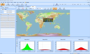
I obtained the global view using two free utilities, wireshark and portmon. Wireshark allows you to capture network packets. I used it to trace an entire connection between HRD running on one computer and its serial server running on another (Windows) computer connected to a radio. This made me realize that following the first 3 messages that establish the connection, there are a number of messages, all 520-bytes long, that probably configure the serial port. They were followed by serial read-write messages, and by a disconnection sequence. The 520-byte messages were all complicated, like the one I could not understand. In the picture on the right you can see a screen shot of wireshark displaying this trace.

I then switched to portmon, a utility that allows you to capture serial-port activity. In the screen shot on the right, you can see a trace of HRD connecting to a radio over a serial port. The important steps are at the top, where HRD configures the port; these steps correspond to the network messages I could not understand.

I was still stumped for a while. The messages just looked too complicated, with random looking binary numbers all over.

At some point, I realized that the fact that HRD configured the remote serial port using so many messages probably meant that it was basically just sending to the server exactly the same operating-system calls that it was making to configure a local port. In principle, HRD could have sent all the information required to configure the port in one message. The fact that it did not suggested that the protocol was designed to keep the server simple and to avoid duplication of code. I then studied the different system calls that Windows programs use to configure serial ports. This allowed me to reverse engineer enough of the protocol to make my server look like the original server to HRD. There are certainly details that I have not figured out yet, but I’m pretty sure I’ll be able to get my radio to run remotely when connected to a Linux box running my server.

The final screen shot is of HRD displaying the welcome message from my server. The window at the back shows diagnostic messages that my server prints. That’s it for now. The current state of things are that the server code has been ported from Java to C (Java is not good for controlling serial ports), and that I still need to test it with the radio. Hopefully I’ll do that over the weekend. Stay tuned.