Partial Restoration of an FT-101E
September 17, 2018 Leave a comment
I finished today a partial restoration of an FT-101E. Here it is, restored and in action, receiving on the 14 MHz band.
As you can see in the video, the unit is labeled Sommerkamp FT-277EX; This is a Yaesu FT-101EX, rebranded for sale in Europe. The transceiver was made in the mid 1970s. It is a hybrid transceiver, using mostly transistors, except for 3 vacuum tubes, the driver and RF power amplifier. The EX model suffix designates an extreme economy model (no DC power supply and speech processor).
The unit belongs to a friend but had no power cord. Restoration therefore started with the power connector. I was fortunate to find components from which to make the connector in a store in Berkeley.

The store did not have the exact connector I needed, but the sales person (probably the owner) found a cable-end male and a panel-mount female and suggested that I modify them to make a cable-end female connector, which is what the FT-101E requires. I did as he suggested. You can see the componets I bought in the picture below.

Here is the final connector powering the radio.

Once I had the connector, I started attending to the other problems the radio had. The most obvious one was a stuck tuning knob. I partially disassembled the tuning knob and discovered that the problem was a 6-to-1 reduction drive. Once it was removed, the rest of the mechanism rotated freely. Almost incredibly, I had in my junk box an identical British-made unit. Unfortunately, the spare unit did not turn smoothly either. I repeatedly cleaned both units with WD-40 and lubricated them. Eventually one started to turn smoothly (I think it was the spare one). I installed it in the radio, which now tunes beautifully.

The next step was to open the radio and to take out the plug-in printed-circuit boards. At this point, I also read other restoration reports and forum posts. As expected, I read that electrolytic capacitors often need replacing. I have already replaced electrolytic capacitors on other old radios, so this was not surprising. Some people wrote that faulty high-voltage capacitors can cause failure of the power-supply transformers, so operating the ratio with the old capacitors seemed outright dangerous.
One difficulty with this radio is that it has A LOT of electrolytic capacitors. Still, I bought the capacitors and removed the plug-in circuit boards from the radio.

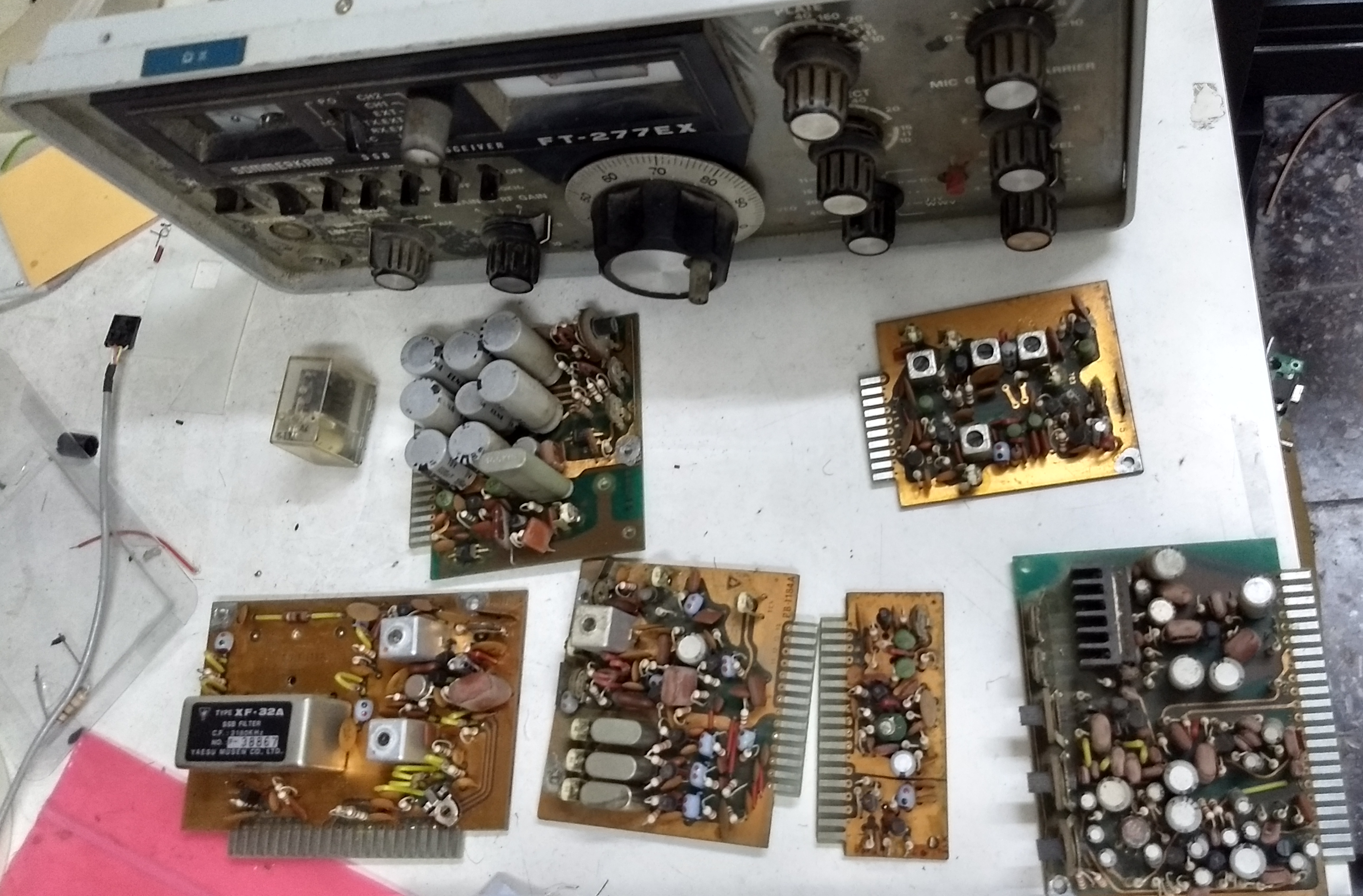

Inspection of the boards showed that the coating of some film capacitors has cracked and peeled.

Possibly a lot of capacitors to replace. I proceeded to removed two electrolytic capacitors from one of the boards and characterized them in a component tester. I also characterized the brand-new replacements. Here is one pair; the original is grey and the new one red.
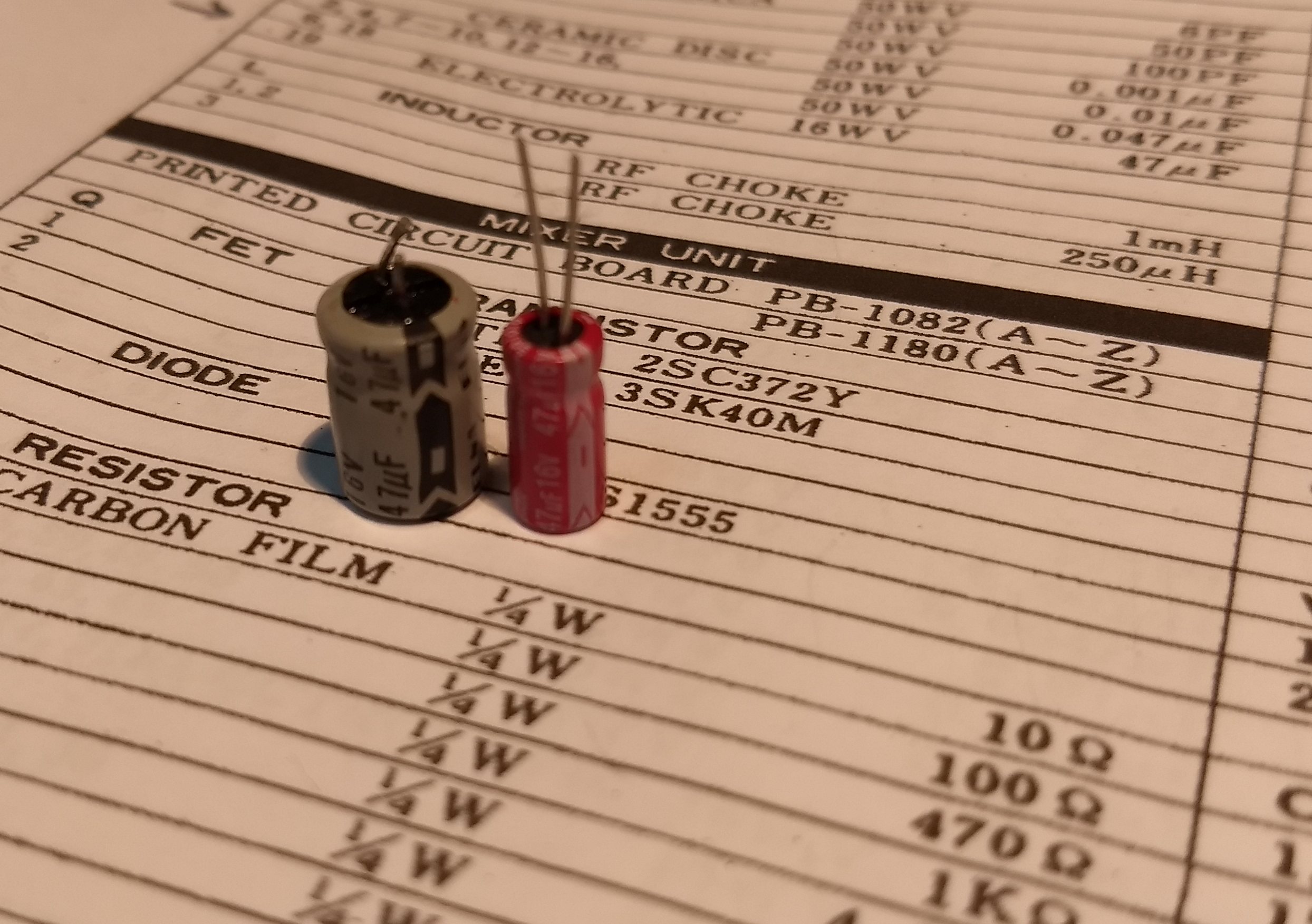
Interestingly, the old capacitors tested better than the new one; comparable capacitance and lower ESR.

I soldered the new replacement capacitors to the board but decided not to replace all the capacitors pro-actively.
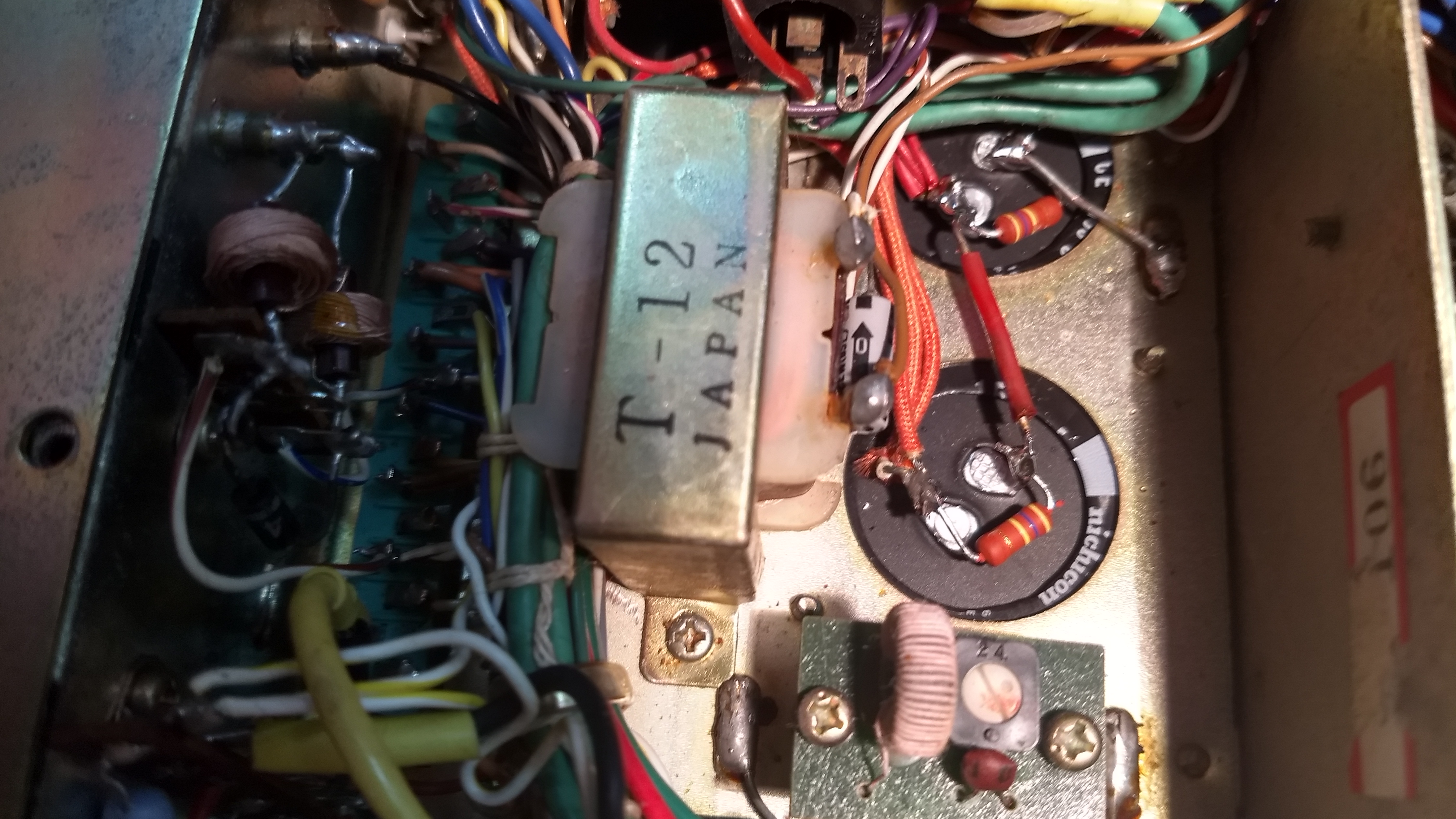
Still, I did replace the two high-voltage capacitors that smooth the supply voltage of the tube RF power supply (~600V), in order to avoid transformer failure. The new capacitors have more capacitance and are much smaller than the old one.

The clamp on the new capacitor is from the old one; they have the same diameter. Replacing them was a bit trick as they are soldered and screwed to the chassis.

The picture above shows the chassis with the old capacitors; the one below shows the new ones installed.
I initially powered the radio with a 12V AC transformer, rather than with 220V, to check that there are no shorts or other catastrophic failures. I was able to measure voltage (about 46V DC) on the high-voltage caps, so I assumed the radio was not shorted.
I wired the connector to a three-prong AC cord and plugged the unit in. Initially the radio seemed dead, but after a short while I realized that the main power switch made intermittent connections. After flipping it a few times the radio woke up and the tuning-dial lamp lit. The AF and RF gain knobs make some scratching noises but there was really no audio. I connected a signal generator; the S-meter reacted but still no audio. Flipping the mode knob between different modes (USB, LSB, CW, etc) resulted in sound in one of them, sometimes. I realized that this switch is also not reliable, so I cleaned it with a contact cleaner, as well as the gain potentiometers.
At that point the radio seemed reasonably functional. I connected it to an antenna and got the results you saw in the video above. The VFO seems very reasonably calibrated; the calibrator works, and so does the preselector and clarifier. The noise blanker seems dead. Volume seems a bit weak, but the radio seems reasonably sensitive. Here are videos that show the preselector and calibrator in action.
I tried to go through the transmitter-tuning procedure. The meter did not react as it is supposed to, so I left this alone for now.
I do not think that the radio is fully function or up to spec, but it does receive, and this is satisfying (I assume it was not turned on for decades). It can probably be fixed further, except if the final tubes are gone or close; they were inexpensive 40 years ago, but replacements are expensive and hard to get today.
It’s been fun.
