Rebuilding a Heathkit HP-23 Power Supply
September 11, 2014 7 Comments
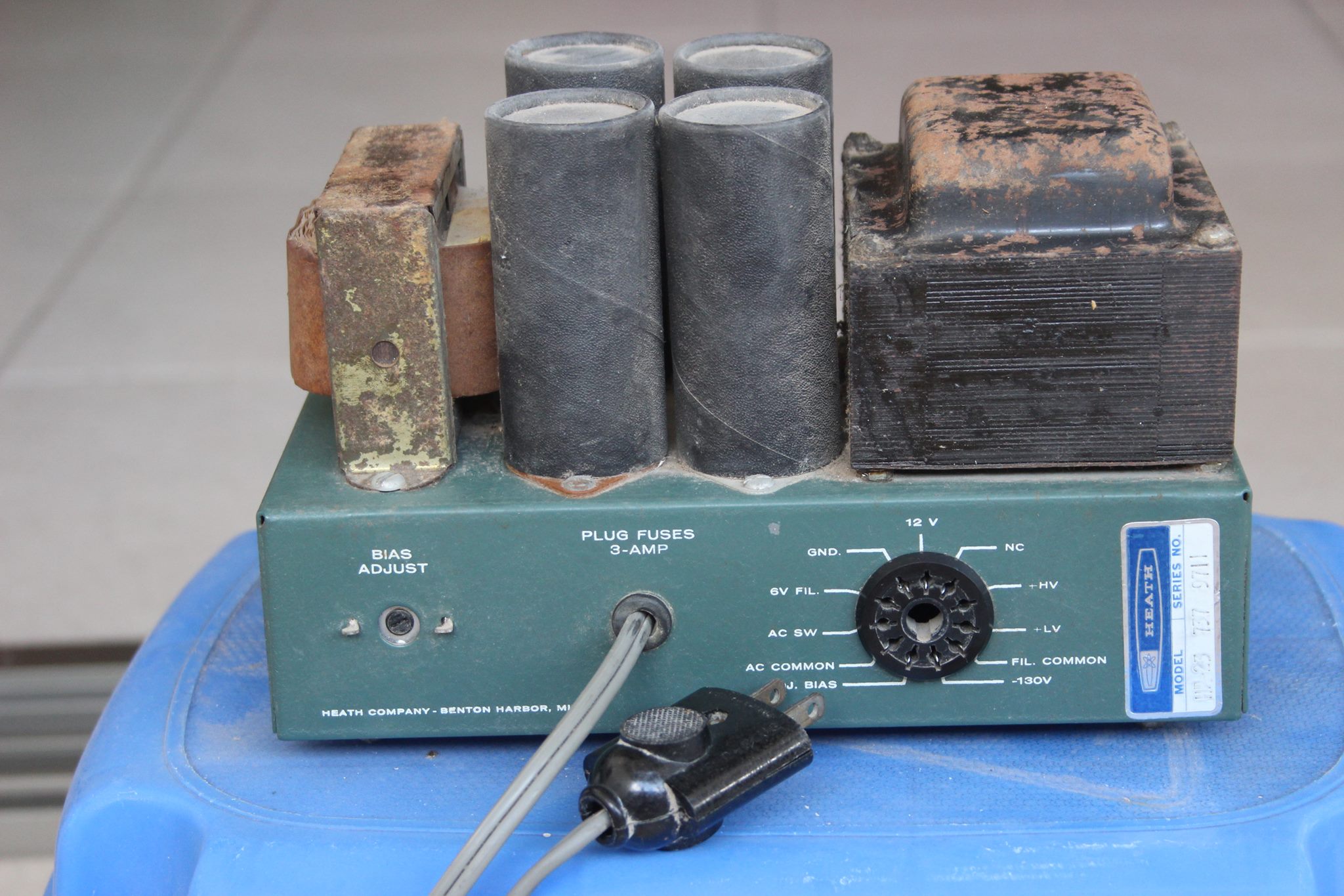
 A while ago somebody gave me an old Heathkit SB-101 transceiver and a matching SB-600 speaker with an HP-23 power supply mounted inside the speaker. They were pretty dirty and the power cable that connects the transceiver and the power supply was missing. I cleaned them up and they came out pretty nice visually. The transceiver has some mechanical problems (missing rubber belts, a melted shaft coupler, etc), so I left it alone for now and decided to restore the HP-23 first.
The power supply looked great after cleaning, except for a minor rust on the metal covers of the transformer and choke. I think that the fact they were covered in dust for a long time (most likely decades) brought on the rust.
In equipment this old there’s a good chance that the electrolytic capacitors are gone. If the caps in the power supply short, this can destroy other components, so it’s not a good idea to just turn the unit on. I did some research on the internet and discovered that there is a procedure to restore old electrolytic capacitors (see, e.g., here and here). But it is slow, requires disconnecting them from the circuit, and it does not always work. So I decided to replace all of them. This brought up two more questions: how to install the new caps, and whether to also replace diodes and bleeder/filter resistors.  The inside of the supply looked clean and in a good shape, but on the other hand these components are inexpensive and easy to replace. Resistors sometimes drift in value, so replacing them might bring resistances closer to spec. Diodes don’t typically suffer significant damage over time, but I could replace the old 500V diodes with 1000V ones. I decided to replace the diodes and resistors, which means that I could really empty out the inside of the chassis which would give more flexibility in terms of installation options for the new caps.
Bob Hanway sells a kit to replace all of these components in the HP-23 and its variants. The kit is based on a PCB that is installed inside the emptied chassis. I decided to use a similar approach and to use a PCB, but to surface-mount all the components. The resistors and diodes and some of the caps I got have leads so they are intended to be mounted in through-hole PCBs like Bob’s, but if you are building by hand it’s easy to solder them to PCB islands on one side of a PCB. This meant that the other side could be all ground and could therefore safely seal the holes in the chassis left after removing the four large caps.
The replacements for the 4 large caps are not through hole, but have snap-in terminals, so my SMD-style mounting method did not work for them. What I eventually decided to do was to solder them to the terminal strips that I removed from the old circuit and to solder the terminal strips to my PCB. Here is what the assembled PCB looked like with all components soldered in.

I started making the PCB with the “hobby knife” method, but it was slow, so I switched to removing copper using a Dremel-like rotary tool with a round diamond head. It was easy and took only minutes. It did generate nasty dust, so if you use it (or in general, if you use these diamond heads on anything), you may want to wear a dust mask.
Here is the circuit diagram of the HP-23.

I replaced the old 2W resistors with 3W units with the same resistance; 1W resistors were replaced with a 2W units. I replaced 125µF 450V caps with 150 µF 450V units; 40 µF 450V with 47µF 450V; and 20 µF 150V with 22 µF 200V units. Diodes are now rated for 1000V and 1A. As you can see in both the schematics and in the picture, the unit came with the original 2-prong AC plug. I decided to switch to a safer 3-prong plug in order to ground the chassis. The fuses in the unit were housed in the plug itself, and this is not possible with modern 3-prong US plugs. I therefore added a fuse holder on the live AC wire. Another improvement I made was to add a switch that switches the low-voltage output between 250V and 300V. This switch replaces the alternate connections that you see on the schematics. This switch came as standard in later versions of the HP-23. I wanted to have this feature because the SB-101 that came with the HP-23 needs 300V, whereas an old SW-32A that I’ve had for a bit over 30 years needs 250V. (I do have a home-brew power supply that used to power the 32A just fine 30 years ago, but it is huge and in a terrible shape, so the ability of HP-23 to power both transceivers is definitely useful.)
With the actual construction over, I was worried about two things. One was the possibility of a breakdown in the old transformer. The other was the possibility that I made a mistake in the construction of the new PCB. The transformer is connected to the mains, and the circuit board is supposed to supply over 800V, so the possibility of faults scared me. I therefore checked transformer and the circuit board separately and carefully. I started the testing of the transformer by connecting the output of an 11V isolated transformer to its primary. That is, the transformer sees 11V at 50Hz (that’s the line frequency here) rather than the 115V at 60Hz it is designed for. I tested the voltage on the secondaries. They were about 10 times lower than specified on the schematics. This told me that the transformer is working. The test AC voltages lower than 30V, so it was very safe. The next step was to test the transformer at 115V, but with a 230V 60W incandescent bulb in series with the transformer (a 115V bulb would have been better but I did not have one). This dropped the voltage on the transformer to about 73V. It still worked fine, which meant that the insulation in the transformer is in a reasonable shape. Michael Luft suggested connecting a bulb in series; even if the transformer shorted, the entire 115V would fall on the bulb rather than on the AC mains. The transformer seemed fine, but is my new implementation of the rest of the circuit correct? I tested each section separately using the 11V transformer. All three (820V, 250/300V, and -130V) worked fine. I mounted the PCB inside the chassis and wired it to the transformer and to the large choke. I again tested everything at low voltages by connecting the primary to the 11V transformer.

Everything worked correctly, at 11V. I was ready to connect the rebuilt HP-23 to 115V. The mains voltage here is 230V, so I needed to use a step-down transformer. I did the first test with a tiny step-down transformer that can only deliver 15W or so, hoping that if something goes wrong, the step-down transformer would go before the HP-23. Output voltages were about right, so I switched to a 500W step down transformer. Everything is still fine, so I guess the HP-23 is working again. The next restoration projects are the two transceivers and the home brewed power supply. I started taking apart the latter while trying to figure out the schematics in the process (I don’t have any documentation on it; from what I have seen so far it is not a copy of the HP-23).
dfk

Very nicely done – just needs a finishing touch of black paint. I liked how you worked around with testing with smaller voltages without using a variac-like variable transformer. Good luck with your restoration project! 73!
Thanks Paul! You are not the first one to suggest that I paint the transformer. I kind of like the fact that the little bit of rust shows the age of the power supply, but maybe it really deserves a coat of paint (like it deserved new caps 🙂
hi Sivan, I also made this psu for “MyToys “hotwater 101 & SB 102. see at https://yc1rhs.wordpress.com/2013/05/21/psu-heathkit-hp-23b/
good project, 73!
How did you get the cardboard off the caps with out tearing it?
Nice restoration job I’m getting ready to restore a HealthKit UT-1 and a HP-23.
Thanks, Dave
Hi Dave, I’m not sure I understand the question. I just removed the caps with the cardboard and all.
Far Circuits sells a circuit board for $12. I bought one at Dayton Hamvention and built it up.
Thanks Chuck. Definitely useful.