Building a CobWebb Antenna
February 19, 2016 1 Comment
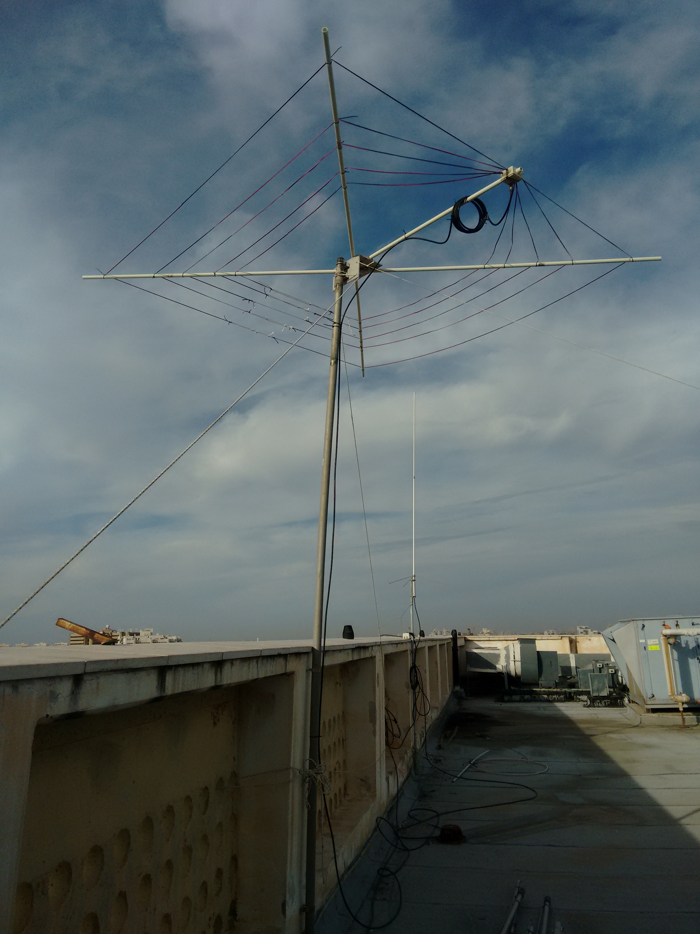 Yesterday I finished building a CobWebb antenna, together with Itamar Melamed. The CobWebb is an HF antenna for the 14, 18, 21, 24, and 28MHz bands. It was designed by Steve Webb, who used to sell it (his web site seems to be inactive). The antenna is basically a fan dipole (five dipoles fed in parallel) in which the dipoles have been folded into squares. The folding makes the antenna compact; it fits into a square with a side of less than 3m. The folding also reduces the feed-point impedance down to something like 12.5 Ohm. The radiation pattern is omnidirectinoal.
 I started the construction from the frame. I wanted the antenna to be rigid and to survive winds, so I built it out of fairly thick fiberglass poles, 25.4mm diameter with 2.85mm wall. The poles are very stiff. I could not find such poles at local distributors, so I drove to the factory that makes them (Pas-Gon), bought two 6m poles and had them cut into two 4m segments, one 1.3m for the feedpoint, and some leftovers. Driving back in a small car with the 4m poles strapped to the outside of the car was interesting (it’s a 2h drive). I decided to use 4m poles in order to achieve maximum strength; you can also make the antenna from four 2m arms.

 The center support is a heavy aluminum bracket. I wanted to have the support made at a workshop, but it turned out that they had something almost suitable that somebody ordered but never picked up. They modified it for me by drilling holes and by cutting part of the aluminum to allow the lower poles to pass through. This part too is very strong and stiff.
There are two ways to feed the CobWebb. Webb’s original design is very clever. It used a balanced T-match to match the 50Ω coax to low impedance at the center of the dipoles. He constructed the antenna from twin-lead multi-strand copper wires, such as the ones used as speaker cables or mains zip-cord. One wire in each dipole is left whole; the other is broken in the middle and connected to the coax. The two leads are shorted some distance away from the center, in each side of the dipole; these are the actual feed points of the dipole. By moving the short towards the center or the ends, the resistance of the antenna at resonance changes. The use of the zip-cord T match makes mechanical sense and it feeds the antenna without any ferrite transformer. The design is well documented in a PDF document on the web, which includes measurements of the elements and the short points (I think the document was put together by Steve Topping, but it is not signed so I am not 100% sure; there is one error in it, reported by Alan Reeves: the sides of the 18MHz dipole should be 4040mm long, not 4400mm).
One builder, Steve Hunt, disliked the T-match arrangement and came up with an alternative matching mechanism: a pair of 1:1 current baluns arranged to create a 1:4 balun. Transforming 50Ω to 12.5 effectively requires a low-impedance transmission line, which Hunt achieved by paralleling two 50Ω coax cables. One aspect of the T-match that worried Hunt was the difficulty of moving the short point to acheive a 50Ω impedance. This is indeed not easy, and I, like many other builders, decided to try out the transformer feed. I was also worried that the optimal short points would depend on the specific properties of the zip-cord and that the measurements of the original design would not work with the zip-cord I decided to use. I built the transformer using RG-142 coax, which can handle a lot of power, and large ferrite toroids. However, the ferrites I used did not function well at 14-28MHz (the transformer did perform well below 1Mhz, but this is not useful for this antenna).
 I decided not to try the original design rather than try other ferrite. Itamar and I started by preparing just the 18MHz wire assembly with temporary short points (not soldered yet) and connected it temporarily to a BNC socket. We hoisted the antenna and measured the impedance with a VNA (vector network analyzer) that we calibrated to the end of the coax. The results seemed good; the resistive part was close to 50Ω and the resonance was close enough to the target frequency that it seemed that by modifying the dipole’s length would tune it.

 We lowered the antenna, built the rest of the dipoles, soldered the short points, built a more permanent feed-point box and connector, and hoisted it back up. Now it was time to tune the dipole’s length. The design uses dipole ends that are folded back, and Reeves advised to make the folded back sections longer, to make it possible to lengthen the dipoles; we did leave them longer. We measured the return-loss (SWR) dips to make sure the short-points were effective, and measured the resonance frequency (really the return-loss dip) at all bands. We calculated roughly by how much we need to shorten or lengthen the dipoles on each band, and tried to do this by changing the fold-back length, but without changing the physical length of the wires. This did not work, so I assume that Alan Reeves is right that the foldback essentially lengthens the dipoles. Next, we cut the elements whose resonance was too low and soldered pieces of wire to elements with resonance too high. This seemed to do the trick. Alan Reeves reported matching problems on 14MHz; our version works fine there too. We lowered the antenna one last time (out of 6 or 7), weather proofed it (I hope), added a coiled-coax choke, and fixed it in place.

 The bandwidth of the antenna is less than spectacular. On 14MHz, the SWR≤3 bandwidth is close to 500kHz, so at the edges of the 14, 21, and 28MHz bands, the antenna might need a tuner.

Such a shame that the origins of this type of antenna are never properly conveyed. Secret is this antennas was first designed and built by Fred Caton vk2abq now sk. He built it using bamboo and ladder line but used coat buttons as insulators creating a quarter cycle phase shift.
I’ve met Fred personally many years ago built a sturdy version of the ABQ and I was away bouncing all over the globe with stations asking me what I was using. Thanks to vk2byf Bob he encouraged me to do the build and the rest is history. The cobweb is chunky and awkward he has the right idea of central feed point but more is needed. My ABQ done 80,40,30,20,17,15,12,10.
And you can build one for 40mtrs if you so desire. If you are seriously interested in can be found in the call book or QRZ.COM and will send you the plan and specs, have fun 73