The arrival of a MSP430 LaunchPad microcontroller kit motivated me to try out something that I’ve been thinking about for a while.

If you look at recent homebrew and kit radios, you find that many of them use an Si570 synthesizer chip as a local oscillator. The Si570 is really something of a wonder chip, so there is no wonder it took over so completely. It is small, very easy to integrate into a circuit, generates a stable square wave (which is what the switching mixers in many recent radios need), and can be quickly tuned by a microcontroller down to a single Hertz. It comes in several versions, but even the simplest one generates frequencies up to 160MHz, which is handy given that most radios divide the frequency by 4 before it is applied to the mixer.
For many applications, including software-defined radios, the Si570 is better than the digital direct synthesizer (DDS) chips that were widely used before the Si570 was introduced.
The only problem with the Si570 is that it is a little expensive. It currently costs around $25 in single quantities, dropping to $17 in quantities of 25 (and getting a bit cheaper at large quantities). Not terribly expensive, but not cheap. I was therefore wondering whether there is a lower cost solution that would still be reasonably simple (it’s hard to beat the Si570 for simplicity).
Trying to stick to the specifications of the Si570 is useless; you need a design just like the Si570, so it is bound to end up more complicated and probably more expensive. You must be less greedy. Two features of the Si570 that software-defined radios for amateur use do not need are the high frequency resolution (something like a single Hertz in the Si570) and rapid frequency switching (10ms for large frequency changes, 0.1ms for small changes). We do not need these features because in a software-defined radio (SDR), you can use coarse tuning of the center frequency and still receive any narrow-band signal within at least 24kHz of the center frequency using DSP. Also, because the fine tuning is down in DSP, the convenience we would loose if the center frequency switches slowly (say in a second or two) is not that terrible. Achieving fast frequency switching and high frequency resolution is difficult; a major part of the solution in the Si570 is an internal oscillator that runs in the 5GHz range. Without going to such high frequency and then dividing down, it is difficult to achieve these goals.
So here is the strategy: for a Softrock-class radio, we will use a phase-locked loop (PLL) that tunes using a resolution of 8kHz, say, and which might lock onto the frequency a little slowly. We will do this by dividing a crystal oscillator down to 8kHz, dividing a variable frequency oscillator by some integer so that it produces 8kHz when tuned to a desired frequency, and lock them. For example, to generate 8.008MHz, we will divide the variable oscillator by 1001.
What I wanted to try is to generate the 8kHz reference and to divide the high-frequency output using a microcontroller. Most microcontrollers have one or more timer-counters that can be used for these purposes. When the LauncPad arrived, I decided to see if I can make this work.
A few words about the LaunchPad: it is a very inexpensive ($4.30) development kit intended to introduce people to Texas Instruments’ MSP430 microcontroller family (it seems to me that TI is selling it below cost). It includes a board that contains both a programming/debugging interface, a microcontroller in a socket, two LEDs and one switch, and pads for connecting other circuits to the microcontroller. In terms of features it is similar to TI’s earlier introductory kit, the ez430, which I have used before, but it is easier to use (because it is physically bigger and has more features) and much cheaper. The LaunchPad comes with two 14-pin microcontrollers from the MSP430 16-bit family. Both are low-end devices with small memories and without many peripherals (one has a ADC and the other does not).
To generate accurate frequencies, I need a crystal oscillator, so I soldered into the LauchPad the 32768Hz crystal that comes in the box. The MCU uses this crystal to generate an on-chip 32kHz signal that can drive the different peripherals on the chip. How do I generate an 8kHz output clock from the 32kHz clock? We can use the MCU’s timer to generate the 8kHz signal, but this would use up the single counter-timer on the MCU, which we need for the PLL’s programmable divider. I decided to use the MCU’s interval timer instead. It can’t generate an ouput signal directly, but it can invoke an interrupt service routine ISR. It can’t invoke the ISR on every tick of the 32kHz clock, only every 64 (or less often). So the ISR runs 512 times per second. The ISR flips the state of an output pin, so the signal we see on that pin is a 256Hz square wave. Not the 8kHz I wanted, but still usable.
Because I used an ISR to generate the reference clock for the PLL, I can’t use interrupts for anything else. Otherwise, the 512Hz interrupt might get a little delayed, if another ISR runs while it needs to be invoked. This will cause jitter in the reference clock, which will cause jitter in the output. We don’t want that, so we won’t use interrupts for anything else.
The programmable divider is easy. We feed the high frequency signal to the TACLK pin of the microcontoller, program the counter-timer to use this external signal as its driving clock, and we program the same counter-timer to output a PWM signal on an output pin. The timer can count up to 65535, so in theory we can handle signals of up to 16.7MHz. The data sheet says that the MCU can only handle input clocks of 16MHz or less, so this sets the limit, not the divider.
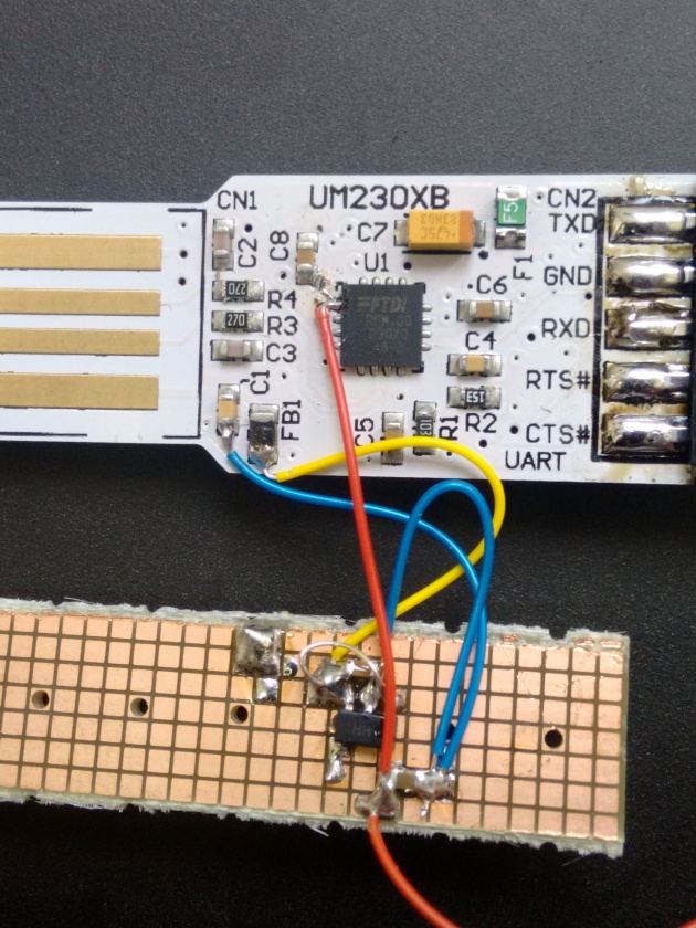
To complete the PLL, we need a voltage-controlled oscillator (VCO), a phase comparator, and a loop filter and/or amplifier. I used a 74HC4046 for the first two, and an RC filter for the third. The 74HC4046’s VCO can go up to about 40MHz (depending on the manufacturer; I used a chip from Philips). It has three different phase comparators, PC1, PC2, and PC3. I used PC2, which does not lock on harmonics of the reference signal. The diagram below shows the overall structure of the loop. Resistors R1, R2 and capacitor C1 set the center frequency and range of the VCO. There are three connections between the MSP430 and the ‘4046, which you can also see in the picture above (using the white, yellow, and brown clips).

I programmed the MSP430 to divide TACLK by 40,000 and the loop locked at 5.12MHz. Changing the divider to 20,000 produced a 10.48MHz signal. The frequency was correct, but was not stable; I basically used a random loop filter, so that’s probably the reason. Another possible problem is that the frequency-setting components I used in the VCO resulted in very wide tuning range, which does not promote stability. But the basic scheme works.
A few comments on the design and where it might go next:
- The main constraint on the frequency that this design can attain is the 74HC4046; the one from Philips can go only up to 40MHz, and devices from some other manufacturers have even lower frequency limits. Since Softrock-style radios divide their clocks by 4, a ‘4046 can only be for RF frequencies of up to 10MHz or so. I am not aware of replacements that would go up to, say, 100MHz or 200MHz.
- MSP430 MCUs from the x2 series can only divide frequencies of up to 16MHz. PICs and dsPICs can go much higher, up to 80MHz in dsPIC33s. However, I think that the asynchronous timer of PICs can’t drive a PWM signal, which means that the divided clock will need to be produced by an ISR; but on PICs it should be possible to generate the reference signal using PWM.
- Slightly larger MSP430s, in particular the MSP430F2274 (which I have mounted on a prototyping board somewhere), have two timer-counters and on-chip opamps. The extra timer should permit an 8kHz reference to be produced, and without using ISRs. It should be possible to use the opamps as loop amplifiers.
- An interesting improvement would be to try to implement the phase comparator in software. Software phase comparators are used in some recent huff-and-puff stabilizers (Hans Summer’s web site contains a fantastic collection of articles on this technique, including some clever designs by Hans himself). My sense is that it would be difficult to respond correctly in software to small phase differences, but perhaps I’m wrong.