Finishing Up the Satellite Yagi
March 26, 2011 2 Comments
 Over the past week I finished the satellite Yagi. I added a VHF Yagi and a band splitter to the UHF Yagi that I constructed first.
Kent Britain, the designer of the antenna, wrote that you can obtain good results with a 2-element 145MHz antenna, but I decided to stay on the safe side with a 3-element antenna, like the one described by Richard Crow. I noticed that Crow’s 3-element antenna was a little different than Britain’s, and decided to build to Britain’s measurements. I first cut the elements out of the same stiff copper wire that I used for the 435MHz Yagi. I was not sure, however, how to combine the two antennas into a single structure. Britain suggested to mount the VHF antenna behind the UHF antenna, on the same boom and on the same plane. This makes it easy to transport and store the antenna, since it is flat, but the boom is pretty long. Crow mounts the antennas side by side; this is easy with his very lightweight construction, but would be harder with wood booms. Shamai Opfer suggested to mount them on separate booms connected by hinges, so I can store them together flat but flip them into a crossed configuration for operating.
I eventually decided to start by mounting them one behind the other on the same boom, and to saw them apart later if I want to try a different configuration. I initially mounted the VHF Yagi 6 inches behind the UHF one, but when I re-read Kent’s article I realized that h wrote that they must be spaced only 3″ apart. So I removed the VHF elements, drilled new holes in the boom, and mounted them in the correct places. I soldered a connector to the VHF Yagi and verified that it was a good match to the transceiver. I was; no tweaking was necessary. I was also able to receive stations communicating using Morse code through VO-52, a satellite with a linear transponder whose downlink is on 145MHz.
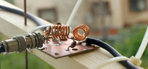
To communicate through satellites with the FT-857, I also needed a band splitter, a 3-port filter that would allow the single VHF/UHF connector of the radio to be connected to the two antennas (you don’t need it if you use separate UHF and VHF radios). Kent Britain’s article describes a simple splitter consisting of two 3-component filters, a high-pass for the UHF port and a low-pass for the VHF port. I did not have capacitors with the values in Britain’s article, so I designed my own splitter with Elsie, a filter design program.
 Elsie has an option to design diplexers, which are band splitters that aim to keep the impedance at one port constant over a large frequency range. Diplexers are used following mixers, for example, where you want a proper termination for the image frequency and to various spurious frequencies that the mixer might output. You can use a diplexer as a band splitter, but if you don’t need constant-impedance termination you have much more freedom to design the low-pass and high-pass filters. I designed the two filters by telling Elsie to design a Chebychev filter and playing with the cutoff frequency and ripple settings until I got the capacitor value I wanted in combination with very little attenuation at in the 145 and 435MHz bands. My capacitors were one 12pF cap for the 145MHz low-pass filter and two 5pF units for the 435MHz high-pass. This generated two inductor values. I then used Elsie inductor calculator to come up with appropriate air inductor designs. I played around a bit to get a sense of what inductance different diameters and turn counts gave. When I got close, I designed the actual filters by specifying the diameter and number of turns. For the UHF filter, I specified 3 turns and a 0.5cm diameter; a length of 0.9cm gave the proper inductance. For the VHF filter, I specified 6 turns and a 1cm diameter, which required a 1.9cm length. I wound the two VHF inductors from the same piece of wire and then bent it so that the inductors were at a 90° angle, to minimize coupling. The UHF inductor was mounted upright, also at a 90° angle from the VHF coils. The wire for all inductors came from a choke from a broken PC power supply.
I connected the antennas and the radio to the splitter and tested the match. I was almost perfect on both UHF and VHF. I could open repeaters on both 145MHz and 435Mhz.
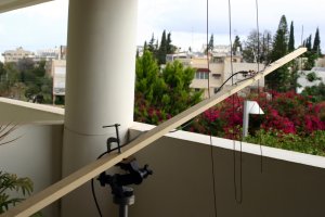
I clamped the wooden boom to a camera tripod, as you can see in the picture at the top. The weight of the antenna is not balanced on the tripod. To relieve some of the force it applied to the tripod’s head, I tied the back of the boom to a leg of the tripod with a cord. It works, but I’ll need to find a better solution.
 The next step was to try the antenna on an FM-repeater satellite. Yesterday two of them passed overhead at reasonable hours, allowing me to try satellite communication for the first time. The first was AO-27, a very old satellite (launched in 1993). It’s web site specifies a schedule, which suggested that only its telemetry beacon would be active when it was over me. I tried to receive the UHF signal nonetheless. When it came over the horizon, I could hear the quieting in the receiver, but then heard a voice station calling. I replied and was able to work that station and 3 more. The next repeater sat to pass over was AO-51, whose repeater is active all the time, and which I was able to hear well when I only had the UHF antenna. AO-51 was much more crowded, with stations transmitting at the same time (and causing severe interference), but I was still able to work a few stations. Tracking the Doppler shift on FM is not hard; I’ll explain the issues in another post. I tracked the location of the satellites by manually rotating the tripod a couple of times during each pass.
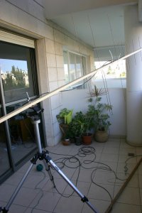
I am very pleased that the antenna allowed me to communicate through the satellites. The antenna is sitting in my balcony. As you can see in the picture, it is essentially indoors, facing a large window. There’s a ceiling above it; the walls around it and the ceiling are all reinforced concrete. From the balcony, about 120° of the sky is visible, towards the east and north. When satellites are to the west or south of me, I can’t see them at all. But in spite of all of these limitations, I was able to communicate through the sats.
Pingback: A Tripod Mount for the Satellite Yagi « Eclectic Technical Experiences
Pingback: Using the USRP with HDSDR « Eclectic Technical Experiences