A small improvement to the DEMI LNA and a UHF J-Pole Antenna
February 22, 2013 1 Comment
 I recently built two more UHF preamplifier kits made by Down East Microwave (DEMI) and a simple reference antenna to go with them.
The antenna and two preamplifiers feed a USRP radio with a WBX front end. The USRP uses a 6V power supply. This created a slight logistical problem for the preamplifiers. They contain a 78M05 linear voltage regulator that drops the input voltage down to 5V. The 78M05 requires an input voltage higher than 6V, which means that the power supply of the USRP cannot power the preamplifiers; I would need a separate power supply for them, one that provides 7V or higher.
This seemed a bit silly when so many low-dropout regulators are available. After searching a bit I found a 5V low-dropout regulator in the same package as the 78M05 that came with the kits (a TO-252 surface-mount package) and with the same pinout; a direct replacement. This regulator, TL720M05 by Texas Instruments, works down to an input voltage of 5.5V and can tolerate even higher input voltages than the 78M05. It does require a larger output capacitor of 22μF or higher; I used 47μF 10V SMD tantalum capacitors which fit on the printed circuit board without a problem. The parts were not expensive and I am happy with the improved functionality of the preamplifiers and the ability to use a single power supply for them and for the USRP.
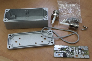
 Incidentally, I ordered these preamplifier kits with the optional enclosure and connectors; they fit together beautifully, as you can see below.
The antenna I built is a simple J-pole, which means it’s a dipole fed from one end by a quarter length matching stub. I computed the length of the stub and the radiating element using an on-line calculator. I left the radiating element a little long for tuning, soldered the coax to the matching stub at the point suggested by the calculator, and tested the antenna for low SWR with the FT-857D. The SWR was a little high. I tried the antenna up and down the 430MHz band trying to see in which direction to tune the antenna (hoping that tuning would require cutting the antenna rather than extending it).  I eventually managed to tune it, but I discovered in the process that a J-pole is not an easy antenna to tune with an SWR meter alone. There are 3 tuning parameters: the length of the radiating element (which you can tune by chopping pieces off the top), the length of the matching stub (chopping pieces off its free end makes the stub shorter and the radiating element longer), and the connection point of the coax to the stub. The first two parameters should bring the antenna to resonance and the third should bring the resistive impedance to 50Ω. Eventually I got it close enough. In the picture on the right you can see the antenna with the coax connected. This short piece of coax is meant to connect the antenna to the preamplifier. Once it was tuned, I added a ferrite sleeve as a choke, put the antenna inside a PVC pipe with some foam to hold it in place (I also tested for resonance inside the PVC sleeve in case it affects the tuning a bit), and the antenna was ready. In the pictures below you can see the coax connection and the two halves of the ferrite sleeve, as well as the antenna mounted with a preamplifier on the roof.


Pingback: A Selective and Robust UHF Front-End | Eclectic Technical Experiences