Toaster-Oven Reflow Soldering without a Controller
January 10, 2014 5 Comments
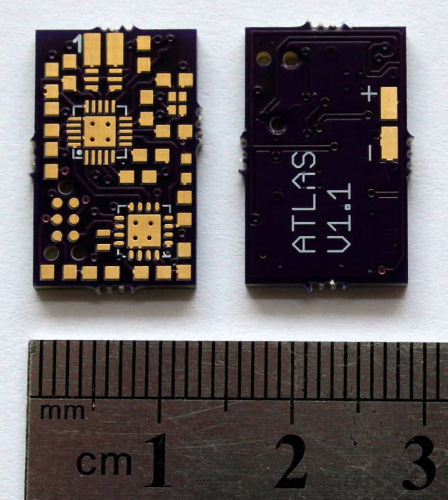
Two circuit boards that I designed with Eagle use tiny components that I knew I could not solder with a soldering iron (chips in QFN packages and others). You can see one of the designs below.
I was aware of two low-cost ways to solder them: with a hot plate, or in an oven. I decided to try to use an oven (mostly because I thought it would be easier, especially with boards that have components on both sides). Ovens designed for soldering (this process is called reflow soldering) are expensive, but I knew that people have successfully converted low-cost toaster ovens to reflow ovens by adding a specialized controller that ramps up and down the temperature at the required rates and brings the board to the required temperature (and hopefully no higher). The results may not be as reliable as a professional reflow oven, but they are fine for prototyping. There is plenty of information on the internet on such conversions: here is one example, a second, a third, a fourth; there are surely many more.
I wondered whether the controller was really necessary. A bit of searching led to a discussion in an online forum in which one of the participants wrote that he uses an unmodified toaster oven to reflow solder. He specified the model that he uses (Cuisinart Exact Heat) and the procedure he uses (convection bake setting, 3 minutes at 300°F, then 2 minutes at 450°F). A little more searching led to a web page at Duke University, where the same model is used to reflow solder in a students’ project lab (with a slightly procedure that also involves monitoring the temperature using a thermocouple). The fact that students can follow the instructions and solder successfully suggested that the process is quite robust and repeatable.
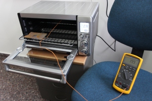
Clearly, this oven can do reflow soldering, but I could not find it locally. It looked like the Cuisinart Exact Heat is a high-end model, so I searched for high-end toaster ovens that I could buy locally. I found the Breville Smart Oven BOV800, which boasted good temperature control like the Cuisinart. Some of its programs allow you to specify a temperature and time, and some include a preheating phase; with preheating, the timer only starts when the oven reaches the set temperature. Other programs are more cryptic and specify things like the number of slices and the degree of browning. Each program runs the heating elements at a different power level, and some use only a subset of the elements, but the manual does not specify these details for every program, only for some. This is somewhat unfortunate, because the power determines the temperature ramp-up rate. But it’s a consumer product, so I guess I should not have expected a detailed specification.
When the oven arrived, I started testing it using a thermocouple (Fluke 87V multimeter with a type-K thermocouple). I used different programs and target temperatures and wrote down the actual temperature the thermocouple every 15 seconds. I compared the results to the recommended reflow profile of the solder paste I have, Chip Quick SMD291AX10. The basic building blocks of the profile are a soak period in which the temperature should ramp up from 140°C to 180°C during a period of 60-90 seconds (at around 140°, the flux activates; at 183°, the solder liquifies), and a 30-60s reflow period, at which temperature should be above 183°C, with a peak at 210-220°C. After that the temperature should drop, and it can drop pretty quickly, although that rate should be limited too.

After a few hours of testing, I settled on a reflow procedure for this oven (and this solder paste). I insert the board(s), insert the thermocouple into the oven, and close the door. I set the oven to the bake program (which uses convection by default, and I leave convection on), temperature to to 160°C and the timer to 1 minute. When the oven beeps that it reached 160° and start counting down time, I turn it off, set the target to 210°, and turn it back on. This adds some soaking time, because the oven has not yet reached 183°. At some point, you see the solder liquify; it turns from dull gray to a shiny reflective metal. This normally occurs when the thermocouple shows around 195°C, but it varies. When the oven beeps that it reached 210°, the thermocouple usually shows a lower temperature. I leave the oven on for about 10 seconds more, aiming for the thermocouple to go above 210°, and then I turn off the oven and open the door slightly, to allow the board to cool. In the first runs I also used a stopper app on my phone to ensure that the soak and reflow periods where within the recommended bounds. The periods I get with this procedure at at the slow end of the recommended bounds, perhaps even a little slower, but not by much.
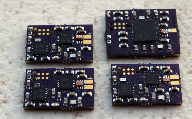
Boards that I soldered with the oven come up out well, but not always perfect. I suspect that the problem is in the application of the solder paste (it’s easy to apply too much), not in the reflow process. Simple boards such as the ones shown in the previous post came up perfect every time. More complex boards like the one shown on the top of this post often suffer from too much solder paste, as you can see in the batch of four boards below (not all identical, but all soldered at the same time; results in other batches were similar).
Almost all the 0603-size resistors, capacitors and LEDs were soldered correctly (the one that didn’t, on the bottom right board, ended up on an alternative ground pad so this did not affect the circuit in any way; this was caused by too much paste). The QFN parts were mostly soldered well, but you can see some solder bridges, like on the left side of the CC1101 on the bottom-left board. These were easily removed using a solder wick. The brown baluns (the 6-pads brown components to the right of the cc1101) were mostly not soldered well. Two pads are shorted on one board, and there are unsoldered pads on others (e.g., on the top-left board). I had to fix these with a soldering iron (not easy, and some baluns got destroyed in the process). I think that in the case of these baluns, the footprint on the board is not perfect and that the pads should extend a bit more below the part; the manufacturer insists that their recommended footprint is fine, but it did not work so well for me.
All in all, I am very happy with this reflow process. Simple boards come out perfect. More complex ones require manual repairs, but the repairs are doable with a solder wick and an iron. The process allows me to solder parts that are either hard or impossible to solder with an iron, and with relative ease. The process is also faster than soldering with an iron, even for parts that I can reliably solder with an iron (0603 passives, SOT89 parts, and so on). I assume that a laser-cut stencil for applying the solder paste would make the process much more reliable, but it works reasonably well for prototyping as is.


Pingback: Hackaday Links: January 12, 2014
I bought the same oven to use for DIY reflow. Did you ever record the rate at which the oven can heat? ie: Deg C/sec . Ideally I’d like it to be in the range of 1 to 3 C/s
Pingback: A Selective and Robust UHF Front-End | Eclectic Technical Experiences
Pingback: Surface-Mount (SMD) Prototyping and Hacking | Eclectic Technical Experiences
Pingback: Toaster-Oven Reflow with Normal Solder (no Solder Paste) | Eclectic Technical Experiences